Author: Frederick R. Vobbe, W8HDU
November 28, 2008
| Antenna 013: 20 Meter Top Loaded Vertical Author: Frederick R. Vobbe, W8HDU November 28, 2008 |
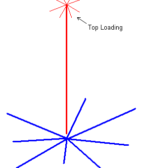
 A top loaded vertical antenna has several advantages over the conventional vertical, but the biggest advantage is that it's shorter in length. A top loaded vertical antenna has several advantages over the conventional vertical, but the biggest advantage is that it's shorter in length.
The ground side of the antenna is a series of radials that all group into a connection at the base of the antenna, and are insulated from the pipe (red part). See the article on the 40 meter basic for more information on grounding and radial installation. The antenna is calculated for a specific length, usually slightly smaller than 1/4 wavelength. The radials should always be the same length, but I have found that you can vary them about,. So on a 20 meter vertical you can have a few radials that are 16 feet (ideal 1/4 wave at 14.1 mHz), and a few at 14, and a few at 18 feet. Radials are crucial in the design of a top loaded antenna as the electrical properties of the antenna require the reaction between the top loaded portion and the ground system. If there is little, or no ground system, then the antenna will vary in load and effectiveness, or may not work at all! Design of a 20 Meter Top Loaded Vertical Let's first calculate what we need. In our 40 meter basic article there is chart at the end that tells us that a basic 20 meter vertical has an antenna height of 16.478 feet. By top loading we can decrease the height to 11.45 feet, (assuming some specifications). For the sake of landing on a design I've chosen a 1.50" tube of aluminum, with a wall thickness of .058", making the inside diameter 1.384". This aluminum is 6061-T6 Extruded Aluminum, and holds up well.
It is made from (8) .188" rods, each 2-foot long. A piece of 1.625" tube, 3" long, with an ID of 1.509" is welded to a 3" x 3", .375" thick piece of 6061-T6 Extruded Aluminum Bar Stock. Imagine a flat plate on the end of a pipe. This slips over the top of our 1.50" antenna pipe. The notch allows it to be slipped in the top of the antenna, and then hose clamped down. Then we weld the rods onto the flat plate arranged in a circle. The rods should extend out at right angles (90-degrees) from the antenna. I got all the aluminum stock from Texas Towers in Plano, TX. Technical Specifications Our 20 Meter Top Loaded Vertical is fed from the bottom, like the basic vertical. It is 11.45 feet tall, and at the top we have eight 2-foot long elements. It does assume a slightly lower impedance for maximum efficiency, in the neighborhood of 30 ohms. Since this is lower than the conventional 50 ohm feed point, a balun or tuner must be used to smooth out the response and make the transmitter a little happier with the load. Below is the VSWR curves. Figure 1 is for 50 ohms, while figure 2 is for 30 ohms.
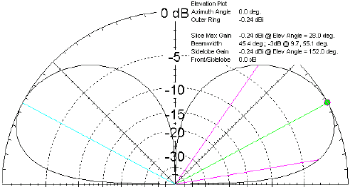
The radiation pattern looks like this;  So now you're asking, what are the differences in these antennas. OK, let's calculate (2) antennas at 14.150 mHz. One with top loading, and the other without.
As you can see, there are very little differences in the performance of the antennas. The biggest difference is the base impedance, (29.01 + j0.8293 versus 35.96 + j0.2730). But what if we change the top load elements? In my example above I used (8) .188" thick aluminum rods, 2 feet long. At any hamfest there is usually someone there selling the 36" long whips that go in the loading coils of antennas. These are typically .05" thick. Here's what happens to our antenna.
By having the longer elements on the top loading we were able to shorten the antenna by 1.15 feet. But the problem most people would have is matching to the 25.55 + j0.04438 load. This is not too hard to do with a simple tuner. Let's look at the RF system. There are three "basic" components to our system. The transmitter, the transmission line, and the antenna. If all are 50 ohms, we have an ideal situation. But let's look at what we have.  Here you see my Yaesu FT-857D. Out of the radio I have a 2 foot cable feeding the VSWR meter. The meter then feeds the transmission line that goes to the antenna. For now we're at 50 ohms. But once the line hits the antenna with the 25.55 + j0.04438 load we have an issue. Our VSWR meter starts to read 2.09:1 because of the difference between in impedance between the antenna and the transmission line. So we add a tuner at the base of the antenna. It's a simple "T" network, but it does the trick. The tuner is a coil from the transmission line (L1), that connects to another coil and a capacitor. The coil (L2) goes to ground, while the capacitor (C1) goes to the antenna. This matches our 50 + j0.0 transmission line to the 25.55 + j0.04438 antenna. 
Doing this makes our 2.09:1 match now read 1.001:1. A BIG improvement! While this may seem a little complicated, the results are well worth the construction and time. Keep in mind that you could use a tuner at the rig, however the tuner masks the mismatch at the radio, and coes not solve the problem of power transfer and matching at the antenna end. Frederick R. Vobbe, W8HDU |
 |
© Copyright 2012 All Rights Reserved - W8HDU |